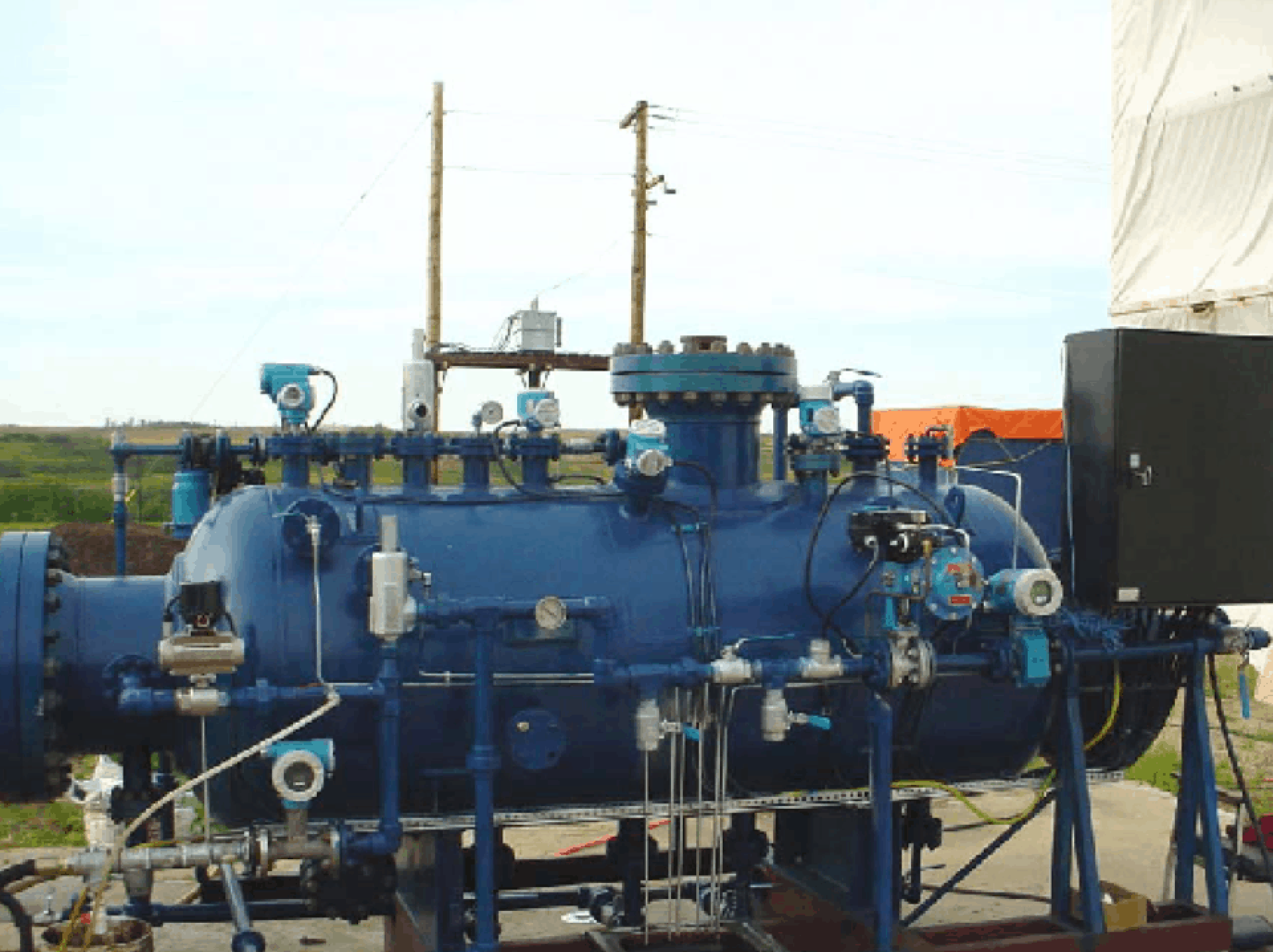
The newly patented Genoil Diamond 3-phase separator is designed to efficiently separate three immiscible phases with different densities, such as associated natural gas, crude oil, water and sand. The system is designed to operate as a self-contained and compact unit that can be used to test oil well production in remote areas. It can be mounted in a permanent location or on a flat-bed trailer and moved from well to well. When the well test separator is towed to an oil well and connected to the wellhead, the ground needs to be fairly leveled to facilitate the good operation of the unit. It connects to a well production line from atop the trailer. Separated oil is returned to the production line while sand and other sediments, gas and water are discharged separately.
The Genoil Diamond well testing system has several advantages over conventional well testing technologies that cannot be utilized as mobile units. Conventional well testing technologies achieve separation by gravity with the fluid heated to elevated temperatures. With large flow rates a significant amount of energy is required to heat the fluid. Providing this heat energy is expensive, and the large amounts required are often only available at batteries. Additionally, in order to achieve gravity separation traditional well test separators require increased residence time, and this inevitably increases their size and renders them unsuitable for transportation to the wells.
Unlike conventional well test separators, the Diamond achieves separation of the three phases with virtually no heat consumption and no chemicals requirements, and the separated oil phase is usually drier and cleaner.
DIAMOND PORTABLE WELL TESTING TECHNOLOGY
GENERAL PROCESS DESCRIPTION AND SYSTEM CONFIGURATION
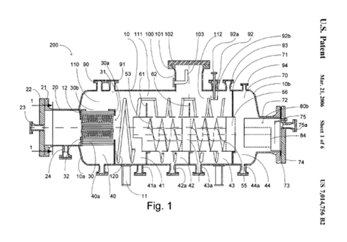
The process begins with the test mixture pumped into a chamber (20) for preliminary separation. Gas is conveyed to the upper portion of the tank with minimal agitation of the liquid whereas the bulk of the oil is removed from the stream.
Corrugated plates (30a) capture the oil droplets, which tend to agglomerate on the underside of the plates. The inclination of the plates facilitates the migration of the oil droplets toward the upper portion of the plates and from there to the oil collection zone (110).
The fluid flowing over the plate corrugations has a sweeping effect that facilitates the removal of the oil from the surface of the plate. The corrugated plates also retain sand, which is thus removed from the fluid. The steep angle of plate inclination (60 0) combined with the sweeping effect of the liquid prevents the formation of deposits. After removal from the fluid stream, solids migrate toward the designated collection area (40) for periodic evacuation.
Gas bubbles remaining in the stream travel through the corrugated pack similarly to the oil droplets. Larger bubbles have an erosive impact on oil drops and solid particles preventing deposits. Smaller gas bubbles collide and attach themselves to oil droplets assisting separation by an air flotation effect.
Gas accumulates in the upper portion of the test separator forming a cushion above the oil pad. As the gas travels along the tank it allows entrained oil droplets to drop in the area where the flow of gas changes suddenly from a horizontal to a vertical direction. A conduit (103) is housed in a chamber designed to drop the velocity of the gas conveniently for further separation of oil from gas.
Liquid exiting the coalescing pack moves downward to a fine-separation stage. The liquid flows in a helical path around specially designed screws (53, 55). The screws are static and impart a helical movement to the liquid. Small particles of oil are removed during the ascending movement of the liquid through specially designed apertures. Furthermore, liquid flowing along the surface of the screws impinges upon small droplets clinging to the surface of the metal and removes them from the stream. Oil then migrates to another oil collection zone (111).
Fines reaching the first screw (53) are rejected during the descendant movement of the liquid through slots into the collection zone (42). The flow is then directed to the lower portion of a coalescing chamber (54). Water is forced to flow upwards and agitates oleophilic balls floating in the chamber. This enhances the coalescing process and assists the balls to self-clean. Larger oil droplets resulting in the coalescing chamber (54) are released into the upper portion of the first screw (53). Nearby apertures allow the oil droplets to travel to the oil collection zone (111) and join the oil layer.
The process of fine separation described above is repeated within the second screw (55) and another coalescing chamber (56). Water containing minute amounts of oil is then directed toward a polishing device (84). Oil droplets enlarged in the coalescing chamber (56) follow the water and rise towards the upper section 112 for periodic removal through another conduit (92a). The flow is then reversed toward the lower section of the polishing device (84) for final separation.
Minute oil droplets reaching the polishing device (84) flow through a bed of ion exchange resins. The bed has an electrostatic charge that is capable of attracting extremely small oil particles. The force of attraction retains the oil particles and forms a film in the upper section of the bed. The flow of water exiting the bed shears-off the oil film. This results in larger oil droplets, which flow upwardly and exit the polishing device (84).
A crescent-shaped space extends along and above the polishing device (84). Water also travels upwardly and assists the migration of the oil drops to another collection zone (80b). The crescent shaped space (80b) above the polishing device (84) curves the path of the water. The flow is reversed smoothly downwards with a velocity and in a fashion that prevent the formation of eddies. This precludes oil droplets reaching the effluent.
Oil separated in the plate pack (30a) enters the collection zone (110) forming a pad. The upper section of the oil pad floats above the water and migrates towards baffles (61, 62) respectively. The oil layer spreads uniformly throughout the oil collection zones (111, 112).
Water droplets and solids contained in the oil pad find it difficult to overcome gravity and follow the oil in a sinusoidal movement imposed by the baffle system. As a result, oil is rendered drier and cleaner.
The operation of the Genoil Diamond well testing unit is controlled by way of a control panel that has a wireless connection to a laptop. The unit, piping, instrumentations and controls are displayed on the laptop screen. The flow rate of gas, oil and water are also displayed on the screen and recorded on the laptopοΏ½s hard drive.
The readings can be sent to interested parties via the Internet. To this end, the laptop communicates with a mobile telephone through a Bluetooth wireless software connection, and the mobile cellular phone connects to an internet ISP. Messages containing attachments with the results can then be e-mailed from the laptop.
GENOIL DIAMOND WELL TESTING TECHNOLOGY
PROCESS FLOW DIAGRAM