- Unique six-stage design for high-efficiency and performance.
- Lowest operational costs of any separator on the market.
- Radical compactness for applications where space is at a premium. Can be placed against bulkheads or in corners.
- Can meet Coast Guard regulations without filter media.
- No internal moving parts offer unsurpassed reliability.
- Very compact units for applications where space is at a premium.
- Simple, unattended operation designed for unattended operation.
- Explosion proof automation (Class 1 Div. 1).
- Versatility for a wide range of applications.
APPLICATIONS
- Bilge water separation for sea-going vessels.
- Off-shore oil platforms.
- Wastewater treatment plants.
- Refineries.
- Gasoline/Diesel service stations.
The Crystal oily water separators are the lowest total costing OWS’s on the market for marine use (Crystal MU model or Crystal SeaTM) are the newest generation of our existing Crystal oily water separation technology. Crystal SeaTM separators are state-of-the-art bilge water separators which have been certified by the US Coast Guard in accordance with the International Maritime Organization Resolution MEPC 107 (49) in 2007. Subsequently, our bilge oily water separators have been certified by the American Bureau of Shipping (ABS).
Genoil Crystal oily water separators utilize a patented, unique process for multi-stage separation of immiscible phases with different densities. An innovative oily water separation process combines gravitational and centrifugal forces with surface tension and vortex effect prior to the polishing stage. A highly effective polishing stage enhances performance and minimizes maintenance costs and downtime.
In 2007 Crystal oily water separators designed for sea-going ships have been certified by the US Coast Guard in accordance with IMO Resolution MEPC. 107 (49). The oily water separator components are precision built, meeting or exceeding the rigorous specifications of classification societies and all Crystal MU models are ABS certified. Due to their high efficiency, the oily water separators are compact and easy to install wherever space is at a premium.
The automation system ensures unattended operation and features PLC units, self-cleaning oil sensors and fail-safe components. The instrumentation and controls are user-friendly and include carefully selected components for exceptional reliability. In custom-built units Crystal oily water separators can be integrated into complex automation systems being operated and monitored from a central location.
Explosion-proof automation (Class I Div. I) for the oil industry is available upon request.
Crystal oily water separators typically achieve effluent purities of less than 5 mg/l for 0-100% oil in water mixtures and relative oil densities of up to 0.985. A specially designed oil dome is also available to reduce the oil content to 5 mg/l at angles of inclination of up to 22.5o in stormy conditions.
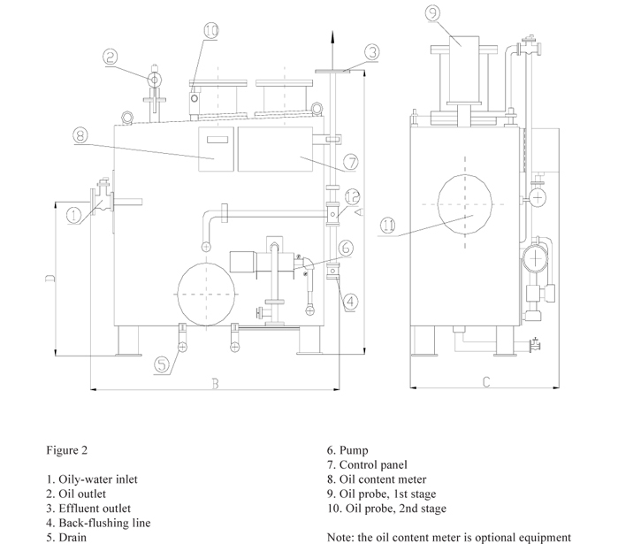
System Configuration
The Genoil Crystal oily water treatment units are designed to separate the liquid phases in six stages located within a single vessel. Each stage is devised to remove oil particles of a certain size and renders the liquid cleaner for the next stage. This ensures greater effectiveness and manageable loads for each stage. Furthermore, it also precludes undue contamination and clogging of various stages by oil, resulting in trouble free-operation.
Minute gas bubbles resulting from controlled vacuum conditions enhance the removal of oil droplets from the water stream. Vacuum is created in the stages operating prior to the circulation pump. Oil is retained at the upper portion of the stages and is gradually accumulated in collection zones.
Downstream from the pump the stages are slightly pressurized. Oil extracted in these stages is transferred continually into the collection zones through specially designed conduits. The transfer of oil occurs due to the pressure differential existing between the stages located upstream and downstream from the pump respectively. Continual oil extraction ensures outstanding cleanliness of the polishing stages and prevents accidental contamination of the effluent.
Oil accumulation in the collection zones is monitored by a probe that initiates periodic oil discharge sequences. The oily water separator is isolated from the effluent discharge line and connected to a pressurized line. Clean water back-flushes the stages and displaces the oil from the collection zones. The oil probe resumes the separation process after a preset amount of oil is evacuated.
The first stage achieves oily water separation through gravity, enhanced through a flotation effect by minute gas bubbles. A specially designed device imparts a rapid circular motion to the liquid. Oil migrates to the centre of the device and then ascends, accumulating progressively in a collection zone (A). Solids and sludge are deposited at the bottom of the stage for removal. Most of the oil droplets are removed in this stage.
The flow is reversed prior to the liquid entering the second stage which contains oleophilic material. Small particles of oil adhere to the surface of the oleophilic beads and are attracted to them by a surface tension effect. As they get together, the oil droplets form larger globules whose enhanced buoyancy overcomes the force of attraction exerted by the beads. The oil globules then detach themselves from the beads, move upwardly with the liquid and remain in the secondary collection zone (B) for removal. This stage is designed to allow continual agitation of the beads in order to accelerate the coalescing process and facilitate a self-cleaning process. The flow is reversed through a circular motion at the upper part of the second stage and oil remains in the secondary collection zone (B).
The liquid is further processed in the third stage entering the core of a circular basket and moving radially outwards through the coalescing material. Liquid velocity decreases towards the periphery of the basket thus allowing minute oil particles to coalesce effectively. The resulting oil globules are retained in a collection zone (C) as the liquid reverses its motion and descends towards the fourth stage.
A positive displacement pump delivers the liquid to the fourth stage for further separation by means of a vortex-generating device. Centripetal forces within the vortex agglomerate the oil particles and force them to coalesce in order to form larger globules. Furthermore, an effect similar to one created by a cyclone also agglomerates the oil particles thus enhancing the coalescing process. A perforated conduit retrieves the globules from the eye of the vortex and directs them to a dispersion plate placed above the vortex generator. Oil particles then travel through suitably sized perforations in the dispersion plate, gather around a funnel and migrate toward the oil collector of the first stage. Spinning liquid rapidly exits the vortex generator being deflected downwards by the dispersion plate.
Further separation of minute oil particles occurs in the fifth stage by means of surface tension within a specially designed device. The liquid flows radially though the device and the oil particles are forced to form clusters of larger globules. The liquid is then directed around a circular baffle devised to create a quiet zone above the device. Oil is readily left behind and then drawn into the first stage as the flow is reversed and cleaner liquid is transferred to the final filtration stage.
In most cases the separation is completed prior to this stage. However, for oils of unusually high density, the sixth stage retains the remaining particles by means of filters. The filters are designed to temporarily retain minute particles of oil on their surface. The particles coalesce and detach themselves from the filter media through their enhanced buoyancy and the sweeping effect of the liquid.
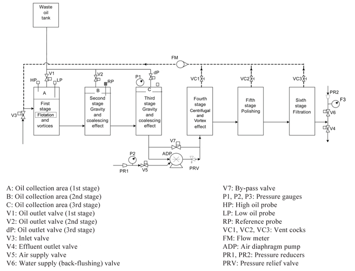
The separation process occurs in six stages in fluid communication with each other as shown below. Oil is gradually removed in each stage and collected in oil zones A, B and C respectively. Periodically, a preset amount of oil is detected by oil sensors which initiate an oil discharge sequence. The liquid flow through the stages is reversed and oil accumulated in the collection zones is then discharged into a waste oil tank.
SEPARATION PROCESS
MAIN FEATURES